Articles
Articles
Code File
Codes & Standards
750V or less transformer bonding and grounding – Code File June 2020
June 16, 2020 | By David Pilon
June 16, 2020 – Why did CE Code Section 10 change the methods of bonding and grounding transformers? Why do we not need a #6 AWG ground taken, unbroken, from each transformer to the ground grid? Why is the system bonding jumper so big when the ground is so small? First, we must understand a few important principles via questions such as: Why do we bond? Why do we ground? What makes the transformer different?
The purpose behind grounding is to set a Near 0 ground potential reference (I’m right here, right now analogy) and stabilize the system. It is also about extending that Near 0 reference to other portions of the installation to establish an equipotential plane (equipotential grounding). The #6 AWG is often overkill, as the bonding conductor—which is sized for the available fault current on the primary side—will have no problem establishing the Near 0 reference. At 750V and less, grounding is not about a fault current return path; that is the purpose of bonding.
Bonding is about interconnecting all metallic equipment and objects, thereby establishing a return path for current imposed on a bonding conductor or metallic equipment (electric or non-electric) which may have inadvertently become energized under a fault condition. This interconnection to the bonding path is what creates the fault return path back to the X0 to complete the circuit and trip the overcurrent device. This is known as a short circuit.
When we install a primary feed to a transformer, the bonding conductor that’s included with the feeder is sized for any potential fault current on the primary side and is substantial enough to establish the Near 0 reference and stabilize the new system.
The new system has no electrical reference establishing it as it is not electrically connected but rather magnetically connected. Therefore, any fault on the new system will only see the new system (Figure 1). Were there a fault on the system prior to the secondary protection, it would cause a magnetically coupled increase in current draw on the primary and trip the primary O/C device, but the fault itself would not be imposed on the bonding conductor of the primary system. The primary system, in fact, only sees an increased current draw that exceeds its capacity. Short circuit to the neutral is shown in Figure 1.
When the fault is to the bonding system, then the system bonding jumper must be sized to conduct the fault on the secondary back to the X0 of the transformer (Figure 2). Here it is shown after the panel, so now the O/C device in the secondary distribution panel will directly see the fault current and trip accordingly. The primary will continue to operate as normal, as it has not had time to magnetically see the rapid increase because the secondary has already dealt with the issue. As such, the rest of the installation continues to operate without issue.
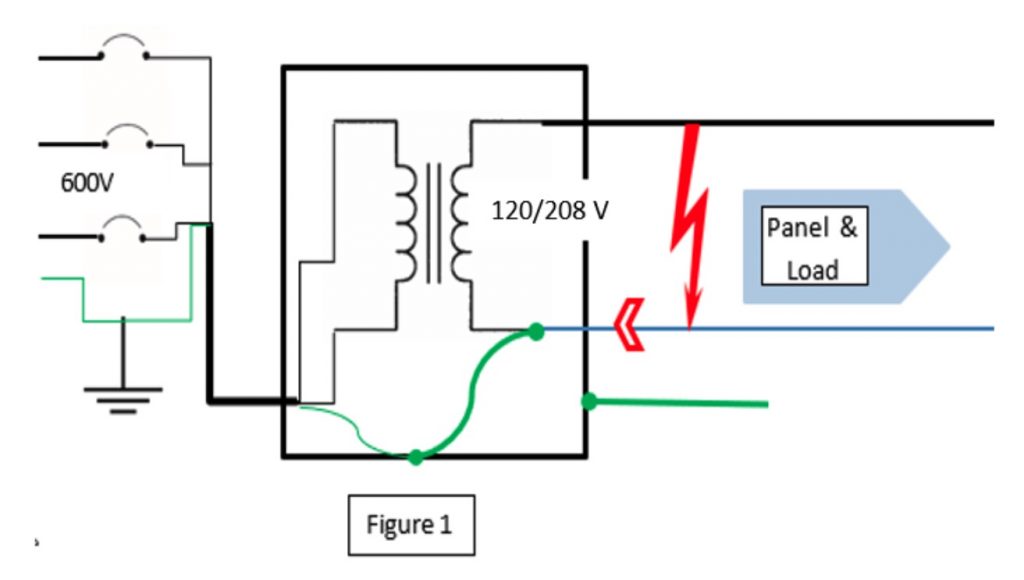
Figure 1
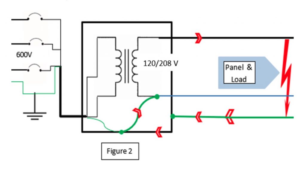
Figure 2

Figure 3a
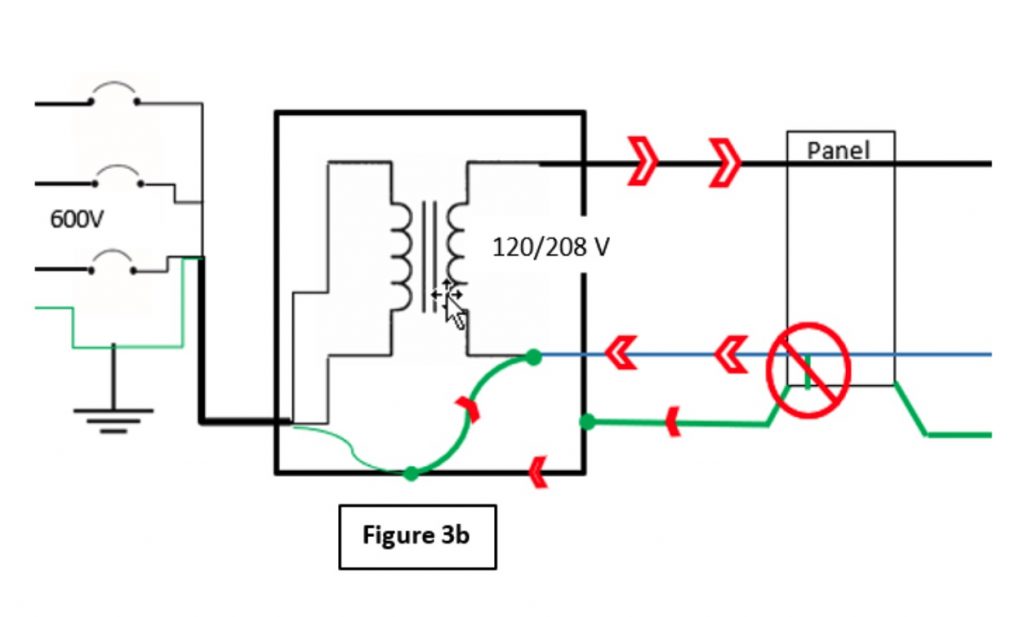
Figure 3b
It is also for this reason that we want to ensure single-point grounding. We need to ensure that the neutral is only grounded in one location—as far back as possible—to set the Near 0 reference and ensure the bonding system and equipment never act as a parallel neutral conductor (Figures 3a and 3b). This can be an issue for equipment operation and potential shock hazard when working around equipment, and the bonding system was not designed for this.
Always consult your AHJ for more specific interpretations.
David Pilon is an electrical inspector with SaskPower, the utility’s training co-ordinator for electrical inspectors and vice-chair of the Canadian Certified Electrical Inspector (CCEI) committee of the International Association of Electrical Inspectors (IAEI), Canadian Section.
This article—along with other great content—appears in the June 2020 edition of Electrical Business Magazine.
Print this page