Features
Articles
Selecting the correct lightning current and surge arrester
September 12, 2016 | By Ruud Roeleveld
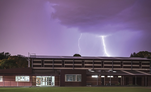 PHOTO: www.shutterstock.com
September 12, 2016 – When selecting the correct lightning current arrester and surge arrester, we first have to perform risk analyses and apply the Lightning Protection Zone concept (LPZ) to determine what the situation requires exactly to protect human lives, buildings and objects, electrical systems, and prevent downtime.
The analyses also indicate what Lightning Protection Level should be used, as well as the location for lightning current arresters and surge arresters. It is a very simple process for smaller installations (i.e. residential and small commercial buildings) but could be more complex for, say, production plants.
One of the most important aspects of modern lightning current and surge protection for electrical systems is the management of high energy lightning currents and low energy surges/transients.
The key to adequate protection is the equipotential bonding of all incoming and outgoing services to avoid any harmful potential difference within the installation.
For example, your PLC is built for a power supply of 120V, which means the potential difference between the hot wire and neutral is 120V. A higher potential difference will damage your equipment. This difference can be initiated by lightning, surge currents from indirect lightning, switching operations in the power supply systems, and/or induction; the electric utility; or internally from the switching on and off of copy machines, motors, etc.
Basically, every time you change the flow of the electron, you will create a surge.
The same situation is applicable for instrumentation wires/installations. The best way to avoid an increase in potential differences is to bond all metal pipes (e.g. water, gas) and all electrical lines (e.g. power, telephone, LAN, instrumentation lines) to an equipotential bonding bar which, itself, is connected with the main ground/earthing system.
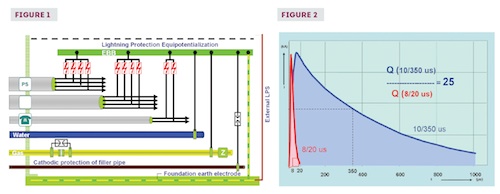
Because electrical lines cannot be connected to ground directly, lightning current arresters and surge arresters are used for indirect grounding, short circuiting the electrical lines to ground during the time of the disturbance (Figure 1).
Requirements for a lightning current arrester
The International Electrotechnical Commission (IEC) defines maximum lightning peak currents in the range of 100,000 amps to 200,000 amps, with a duration of some 100 µs, finally described by a 10/350 µs waveform (Figure 2). Considering the grounding system will be able to absorb about 50% of this energy, about 50,000A to 100,000A of lightning current could be fed into the installation, which means each lightning current arrester has to handle somewhere between 12.5 kA to 50 kA per pole for a couple of 100 µs, depending on the power system (2-, 4- or 5-wire).
For example: 50 kA divided by 4 wires means you will need a lightning current arrester (10/350 µs waveform) with a minimum discharge capability of 12.5 kA per pole, or 50 kA in total when it concerns one pack of 4 poles (sometimes called lines or modes).
Requirements for a surge arrester
Surge arresters have always been tested with an 8/20 µs waveform (introduced by the Telcordia/Bellcore standard, back in the day) to simulate induced transients caused by no direct flashes into the structure. A comparison of these two waveforms (Figure 2) shows the charge of a lightning current (10/350 µs) is much higher than the charge of an induced transient (8/20 µs) at the same peak current level.
On a mathematical basis, this relation is about 25! Consequently, a surge arrester (8/20 µs) is not capable of discharging a lightning current (10/350 µs).
Most of the arresters are parallel devices, which means we have to select devices on line-to-ground voltage. For a 347/600V system, the line-to-ground voltage is 347V, so the operating voltage for the device will be 347V, not 600V.
With respect to discharge capability, we tend to say the higher the better, but also more expensive. A more reasonable approach is to determine what is really needed and how much current can be expected. The Lightning Protection Zone (LPZ) concept can assist you with this process.
Any manufacturer of lightning current and surge arresters is required to publish the above parameters, such as the test wave form 10/350 µs or 8/20 µs on either the product or product data sheet. N.B. joules alone is insufficient!
Arrester life expectancies
Lightning current arrester are based primarily on switching technologies like the RADAX modern spark gap. These components are capable of discharging lightning currents based on the waveform 10/350 µs. Modern spark gaps are not sensitive to degradation and have a long life expectancy.
Surge arresters are based on voltage-limiting components, such as the MOV (metal oxide varistor) technology or a combination of MOV and SAD (silicone avalanche diode). The advantage of an MOV is that it is quick to respond and can discharge a reasonable amount of energy. The disadvantage is that all MOVs have a so-called “aging” process. Surge arresters based on MOVs will fail over time, and will need to be replaced. The life expectancy of such a device is determined by the number of discharges, the amount of energy involved and the quality of its components, as well as the environment to which it is exposed.
Besides discharge rating and waveforms, the clamping voltage or protection level is also regarded as a major parameter that needs to be taken into account. But what is the maximum acceptable protection level voltage?
Fortunately, IEC 60664-1 “Insulation coordination for equipment within low-voltage systems – Part 1: Principles, requirements and tests” gives us an indication: the impulse voltage rating is 800V for a 120V power system, and 1500V for up to 347/600V.
Consequently, these levels are taken as the limits in most countries for maximum protection level voltage. Lightning current arresters and surge arresters with a lower protection level voltage or clamping voltage than the above values (which are based on power systems) are suitable and safe to use in an electrical installation.
Combining lightning current arresters and surge arresters
Lightning current arresters are mainly installed at the main service entrance, which is where we can expect lightning currents. You can use both lightning current and surge arresters at the same location when they are energy-coordinated with one other. Basically, the surge arresters will not be exposed to lightning currents. A manufacturer has to confirm energy coordination between the different types of devices is achieved. Another option is to use a one-unit combined lightning current and surge arrester.
Summary
Equipotential bonding is the key to adequate protection. The Lightning Protection Zone (LPZ) concept is a systematic approach for determining the potential risks and what the situation requires with respect to the use of lightning current arresters (10/350 µs), surge arresters (8/20 µs) or both.
The required discharge capability of a device should be calculated and devices should be chosen based on the calculated value rather than going for the highest bidder and, conceivably, a higher cost. A protection level or clamping voltage lower than 800V for 120V systems (and up to 1.5kV for 347/600V) is sufficient.
Ruud Roeleveld is the president of R3&A Limited, an independently owned Canadian company specializing in lightning and surge protection, and domotics (home automation) systems.
Print this page