Articles
Features
Articles
Code File
Codes & Standards
Code File December 2020 – Grounding basics: Multiple neutral ground connections
December 7, 2020 | By David Pilon
December 7, 2020 – To get a proper handle on grounding, it is vital to understand basic circuitry, magnetism and system isolation. Let’s start with some laws.
Per Ampere’s Law, current flows in closed loops. The return current may split between numerous available paths, with the amplitude in each inversely proportional to the impedance of the individual path. In addition, unintended currents created by external events (e.g. power faults) can also travel along these same paths (1).
That’s a mouthful, but it helps us understand why we are moving away from re-grounding the neutral of any system after it has already been grounded (single-point grounding).
Let’s now look at magnetism. As current flows through a XFMR’s (transformer’s) primary circuit, it creates a magnetic field that induces a current in a second coil. So the current in the secondary is created by the current in the primary, even though it is not a part of the primary’s closed loop.
This means that the current in the primary cannot flow in the secondary loop, nor can the current from secondary flow in the primary loop. Were we to connect the primary and secondary at one point, they still would not be able to impose them-selves on one another.
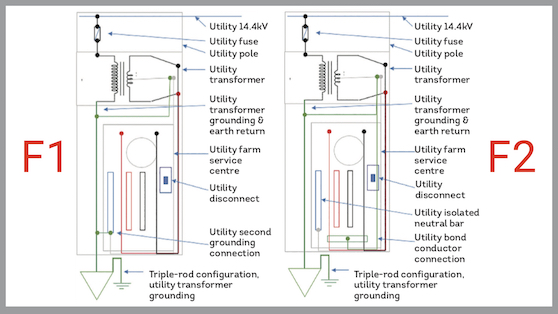
In Figure 1, note the high-voltage earth return has a parallel path through the neutral, which feeds into a farm service centre. Under normal system operation, current will flow from the HV earth return on the neutral through the short bonding jumper, from the cabinet to the grounding conductor.
By installing a second conductor from the single-point grounding connection at the XFMR—running independently of the grounding conductor to the cabinet—we remove the parallel path and establish a system without using the LV neutral as an earth return for the HV system. (See Figure 2 for the proposed 4th conductor added by the utility.)
Multiple neutral grounds at a facility are bonded together by the grounding electrode system. When separate “made” electrodes are required, then the earth connection becomes a parallel grounding path. Most of the current flowing in the grounding electrode system will, therefore, stay in the conductors and not flow through the earth (which makes livestock very happy).
When the bonds between portions of the grounding electrode system are inadequate, then the neutral current can overheat poor connections, and even corrode certain metal junctions. Overheating can create a shock hazard and, in some cases, start fires (2).
By isolating the neutral from the grounding system and running a 4th conductor, the utility actually increases the safety of the installation. Adding an independent conductor that will be connected to the customer’s grounding system increases the effectiveness of the utility ground, and provides the multiple grounding electrodes upon which the system relies.
David Pilon is an electrical inspector with SaskPower, the utility’s training co-ordinator for electrical inspectors and vice-chair of the Canadian Certified Electrical Inspector (CCEI) committee of the International Association of Electrical Inspectors (IAEI), Canadian Section. He can be reached at dpilon@saskpower.com.
Always consult your AHJ for more specific interpretations.
References
1. Lock, E. B.-S. (2010). Grounds for Grounding, IEEE. John Wiley & Sons.
2. Lewis, R. M. (1990). Grounding and Shielding in Facilities. John Wiley & Sons.
This column—along with other great content—appears in the December 2020 edition of Electrical Business Magazine.
Print this page