
October 7, 2009
Submitted by O-M6 TECHNOLOGIES
 To ensure an optimal contact between two connectors, the interferometric analysis measures the important geometric parameters on the surface of the connector.
Geometry of the ferrule
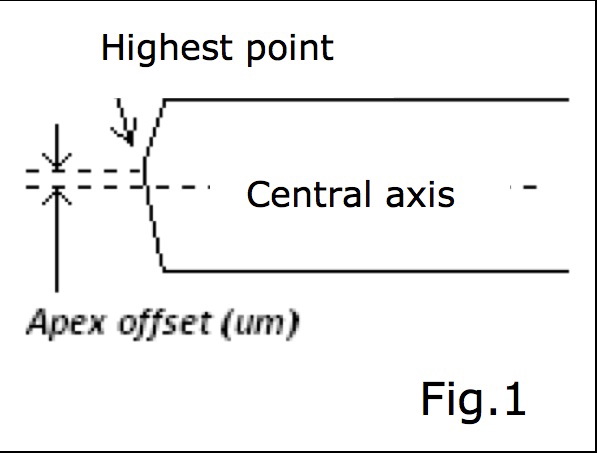
Apex offset
The apex offset is defined as the distance (um) between the
central axis of the fiber and the highest point on the ferrule end-face
(Figure 1).
Radius of curvature
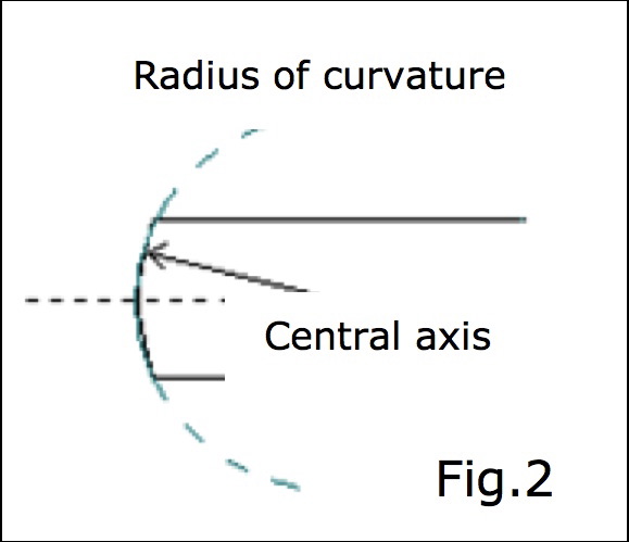 The radius of curvature is defined by the length (mm) of the
radius on a virtual circle with its point of origin on the central
axis, which embraces the shape of the dome produced through polishing
(Figure 2).
The radius of curvature should be 10 mm to 25 mm, except for angle connectors (APC), which must be between 5 mm and 12 mm.
Fiber height
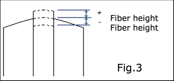 The fiber height is the position of the fiber relative to the
ferrule end-face (nm) (Figure 3). The negative values refer to undercut
(fiber recessing the ferrule), and positive values refer to protrusion
(fiber exceeding the ferrule). The fiber height must be at ± 50 nm.
Concentricity and eccentricity
When the geometric control of the ferrule optimizes the contact between
ferrules during the mating, this does not necessarily mean that the
coupling between the two connectors will be optimal. To optimize the
coupling, we must focus our attention on centring the core with respect
to the external diameter of the ferrule, which is known as the
eccentricity and concentricity of the core.
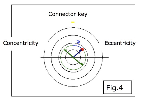 The eccentricity or “decentring” of the core in regard to the
centre of the ferrule is described by the distance of the core to the
centre of the ferrule and an angle in regard to the key.
Concentricity can be represented by a circle having its centre in the
middle of the ferrule, and corresponds to twice the value of the
eccentricity (Figure 4).
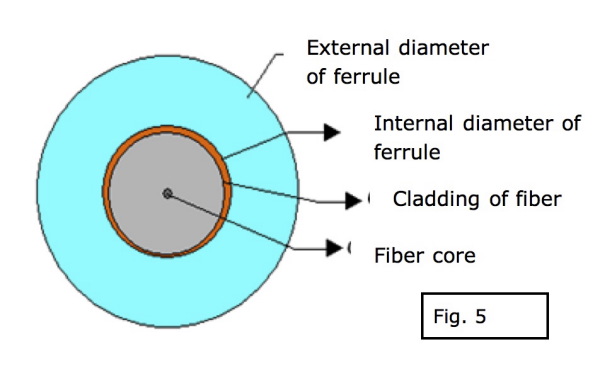 For all practical purposes, the parameters that can influence
the eccentricity of the fiber core with respect to the external
diameter of the ferrule are as follows (Figure 5):
• fiber hole/external diameter
• concentricity “core/cladding”
• tolerance of the internal diameter of the ferrule
• tolerance of the cladding diameter.
{mospagebreak}
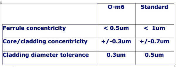
Singlemode reference patch cords (1310/1550 nm) are assembled with
components that meet specifications that are much higher than the
normal standards (Table 1: Features of the fiber and ferrules used to
assemble singlemode reference patchcords [1310/1550 nm]).
 For some connectors, there is an adjustable version that
allows us to control the angular parameter of the eccentricity to bring
the fiber core near 0° (region of the key Figure 4).
Tip: The use of best concentricity ferrules is not only limited to
reference patch cords; they can also be used with an adjustable
connector to improve the coupling of smaller core fibers.
Print this page