Articles
Features
Energy & Power
Transmission & Distribution
Vehicles
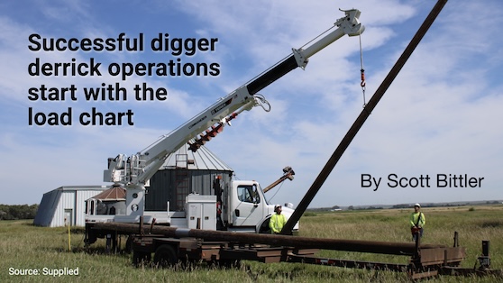
Successful digger derrick operations start with the load chart
January 2, 2024 | By Scott Bittler
Dig holes, set poles and more... safely
January 2, 2024 – Just like when operating cranes, understanding how to read load charts—and applying that information—is critical in the operation of a digger derrick.
In many ways, digger derricks are similar to cranes… telescoping and rotating booms, jibs and other attachments, and winches with load lines that can be configured with multiple parts of line. Applying load knowledge will help with the safe operation of this equipment (not to mention help one become a certified digger derrick operator).
(As a national service trainer with Terex Utilities, my examples will involve Terex equipment, but you can just as easily transfer these same examples to whichever equipment is found in your fleet.)
Digger derrick load charts are designed specifically for the serial number of the unit being used. So just because your fleet may involve more than one Commander C4042, the same load chart may not be used for all units. The nature of the industry is that digger derrick capacities are directly affected by the chassis upon which the equipment is mounted, plus its mounting configuration, not to mention any additional options and accessories with which the digger derrick came equipped.
While load charts are affixed to the device in view of the operator near the controls, it is critical to always verify that the serial number on the load chart matches the serial number of the unit. The load chart for that unit takes into consideration all of the options installed on the boom when the digger derrick was built.
When additional options are added to the digger derrick, it naturally increases the weight of the booms. The digger derrick must be re-stability tested, and a new load chart must be created to account for this extra weight.
Important terminology
The rated capacity of the digger derrick is the maximum working load permitted by the manufacturer for the boom configuration and boom position. Such boom position factors include load radius, boom length, boom angle, and other parameters of use. The rated capacity will be different, depending on where in the load chart you are working, how many parts of line are used, and other factors (e.g. type of rope installed).
To begin, here are some important terms that every digger derrick operator must understand:
Load radius: The distance from the centre of rotation of the digger derrick to the centre of gravity of the load.
Gross capacity: The maximum weight that a machine is designed to lift, which includes the load, attachments, and all rigging. This value is found on the load chart.
Net capacity: The maximum weight that can be lifted. Net capacity is calculated by subtracting the weight of the rigging and added attachments from the gross capacity found on the load chart. The maximum weight of the allowable load to be lifted cannot exceed net capacity.
Determining the load
When teaching this concept to students, I compare it to their paycheck. Each paycheck starts with gross pay. After all deductions (e.g. taxes, insurance), they are left with their net pay; just as net pay is what they get to spend, net capacity is the weight that is left over… the weight that they can actually lift.
Now, let’s talk about the load. You have to consider more than just the weight of the transformer, pole, or cable reel, which is the net load. Gross load is the total weight of the transformer, pole, or cable reel plus the weight of the rigging.
You must consider everything that is suspended on the load line as part of the gross load—shackles, slings, etc. So, while net capacity is key, gross load is extremely important. The total weight of the load, attachments, and rigging must stay within the capacity shown on the load chart.
The Terex load chart (below) displays the gross lifting capacity which, in this case, is based on the options at the boom tip, and the auger being stored on the main boom. The auger size is listed as an option on the chart, so operators know what was included when the chart was created. Should they increase the auger size, they need to deduct the weight difference from their gross capacities. If they do not want to make the deduction each time, a new load chart would be required.

Literally, a moving target
Load charts show information about the gross capacity the digger derrick can lift given various criteria; for example, whether the boom sections are extended or retracted, the boom angle, as well as in which zone you are working. Terex digger derricks offer two zones representative of lifting: over the side of the truck or the rear. It is not recommended to lift over the cab.
Figure 1 shows a Commander C4042 that has been set up with the 3rd boom section extended and the 2nd boom section retracted, with the boom at 45 degrees. The digger derrick load capacities are 5,050 lb in Zone A (rear of truck) and 4,020 lb in Zone B (left or right sides of truck).
However, when both boom sections are extended—and the load radius goes from 17.7 feet to 23.4 feet—the load capacity drops to 3,150 lb in Zone A and 2,510 lb in Zone B.
Because the allowable load may change based on path of lift, it is important that operators plan out the intended load movement from picking to setting. Maybe you are picking up a transformer off the trailer parked behind your digger derrick, intending to rotate to the side and lift it to the top of a pole.
Your lifting zone, load radius, boom angle, and number of boom sections that are extended will change through the full lift as the load moves from picking to setting.
Always make sure your capacity is sufficient through the entire range of motion and various boom positions. It is important to remember that if any boom section is extended—even by an inch—it must be considered fully extended when reading the load chart.
Additionally, some companies may have policies that require digger derricks to operate within a certain percentage of maximum capacity. Make sure you account for those percentages when planning your net capacity and gross load weights.
Load lines
Different types of load line have different capacities, and the load chart provides information about the line working load limit required. When replacing ropes, follow the information on the load chart for rope strength and elongation. Always replace the rope with equivalent type—synthetic or wire—and capacity. The rope length must be long enough to reach the ground in the intended single or multipart configuration.
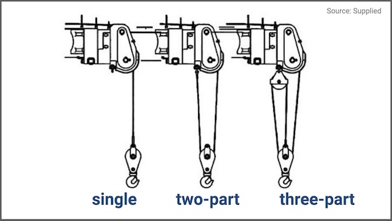
The number of parts of line is critical to the capacity of the line itself. Digger derricks are frequently used with a single part of line. But loads that weigh more than the amount shown on the load chart for single part capacity require that the load line is set up for multiple parts of line, as needed.
There is a mechanical advantage to having multiple parts of line; while multi-parting does not increase the capacity of the load line, it does allow higher loads for the digger derrick up to the load chart capacity.
In Figure 2, the single part load line capacity is 8,052 lb. If you are lifting a load greater than this—but are still within unit gross capacity—you will need to multi-part the load line. Two parting will give you 16,104 lb, whereas three parting will allow 24,156 lb—again, so long as you remain under the digger derrick’s gross capacity.
Final reminders
All of this is well and good, but if you don’t know the weight of the load to be lifted, the planning is worthless! Some digger derricks are equipped with load line indicators; if not, it is an easy and good practice to use a dynamometer to measure the weight of unknown loads.
One last reminder. While digger derricks and cranes have a lot of commonalities when it comes to understanding load charts, there is one critical difference: digger derricks require that the outriggers are correctly deployed. The actual setup and outrigger adjustment can only be performed by the person at the worksite.
Make sure to properly position the digger derrick on firm, level ground and set the outriggers as per the Operator’s Manual on outrigger pads before beginning operations. If the digger derrick is not level, your capacity is reduced.
Everyone wants the satisfaction of doing the job efficiently and safely. One of the best ways to achieve this is to plan every lift carefully, remembering that successful digger derrick operations start with the load chart.
Scott Bittler has been with Terex for 30 years in a variety of service tech roles and, for the last 17 years, has served as a national service trainer and technician with Terex Utilities. He is a Terex Utilities accredited instructor and a certified mobile hydraulic mechanic and accredited instructor.

You’ll find all Back Issues of Electrical Business Magazine in our Digital Archive.
Print this page